Keys, Modules and Engine Controllers for 2022 Ram 3500
Categories
- Battery, Battery Tray and Cables
- Generators/Alternators
- Horns
- Ignition, Spark Plugs, Cables, Coils, and Glow Plugs
- Instrument Panel Cluster
- Keys, Modules and Engine Controllers
- Lamps, Interior and Exterior
- Park Assist
- Power Distribution, Fuse Block, Junction Block, Relays and Fuses
- Radio, Antenna, Speakers, DVD, and Video systems
- Sensors
- Speed Control
- Starters
- Switches
- Telecommunication
- Wiper and Washer System
- Wiring, Body and Accessories
- Wiring, Headlamp to Dash
- Wiring, Instrument Panel
- Wiring, Powertrain
- Camshaft and Valve
- Crankcase Ventilation
- Crankshaft, Piston, Drive Plate, Flywheel, and Damper
- Cylinder Block
- Cylinder Head
- Engine Identification, Service Engines & Engine Service Kits
- Engine Mounting
- Engine Oiling, Oil Pan and Indicator (Dipstick)
- Manifolds and Vacuum Fittings
- Timing Belt/Chain and Cover and Balance Shaft
- Carpets, Floor Mats, Load Floor, and Silencers
- Consoles
- Door Trim Panels - Front and Rear
- Front Seats - Adjusters, Recliners, Shields and Risers
- Front Seats - First Row
- Headliners - Visors - Assist Straps
- Instrument Panel
- Panels - Moldings - Scuff Plates, Pillar, Cowl, 1/4 Panel Trim and Cargo Covers
- Rear Seats - Second Row
- Rear Seats - Second Row Adjusters, Recliners, Shields and Risers
Browse Categories
Select category
- Battery, Battery Tray and Cables
- Generators/Alternators
- Horns
- Ignition, Spark Plugs, Cables, Coils, and Glow Plugs
- Instrument Panel Cluster
- Keys, Modules and Engine Controllers
- Lamps, Interior and Exterior
- Park Assist
- Power Distribution, Fuse Block, Junction Block, Relays and Fuses
- Radio, Antenna, Speakers, DVD, and Video systems
- Sensors
- Speed Control
- Starters
- Switches
- Telecommunication
- Wiper and Washer System
- Wiring, Body and Accessories
- Wiring, Headlamp to Dash
- Wiring, Instrument Panel
- Wiring, Powertrain
- Camshaft and Valve
- Crankcase Ventilation
- Crankshaft, Piston, Drive Plate, Flywheel, and Damper
- Cylinder Block
- Cylinder Head
- Engine Identification, Service Engines & Engine Service Kits
- Engine Mounting
- Engine Oiling, Oil Pan and Indicator (Dipstick)
- Manifolds and Vacuum Fittings
- Timing Belt/Chain and Cover and Balance Shaft
- Carpets, Floor Mats, Load Floor, and Silencers
- Consoles
- Door Trim Panels - Front and Rear
- Front Seats - Adjusters, Recliners, Shields and Risers
- Front Seats - First Row
- Headliners - Visors - Assist Straps
- Instrument Panel
- Panels - Moldings - Scuff Plates, Pillar, Cowl, 1/4 Panel Trim and Cargo Covers
- Rear Seats - Second Row
- Rear Seats - Second Row Adjusters, Recliners, Shields and Risers
Keys, Modules and Engine Controllers for 2022 Ram 3500
 1. Blank Key
  2. Blank Key
 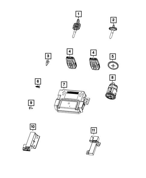 3. Blank Key
 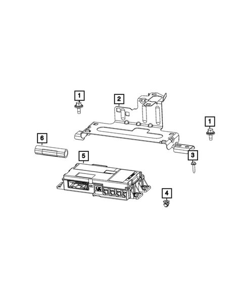 4. Screw
  5. Screw
  6. Screw
  7. Body Controller Module
  8. Tapping Round Head Screw
  9. Tapping Round Head Screw
  10. Tapping Round Head Screw
  11. Heated Seat Module
  12. Tie Strap
  13. Occupant Restraint Control Cover
  14. Engine Controller Module
 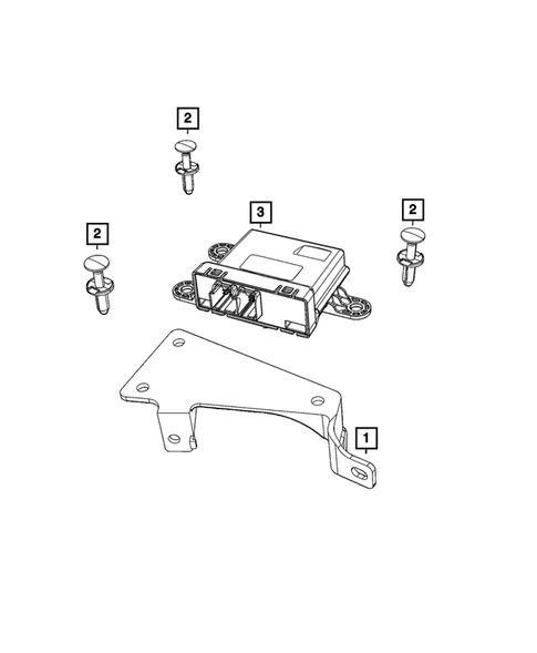 15. Module Bracket
 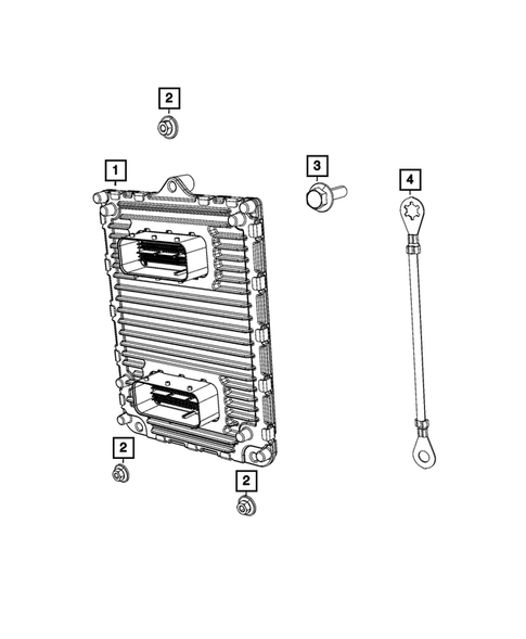 16. Engine Controller Module
  17. Vehicle Systems Interface Module
  18. Engine Controller Module
  19. Module Bracket
  20. Engine Controller Module
  21. Engine Controller Module
  22. Gateway Module
  23. Engine Controller Module
  24. Body Controller Module
  25. Camera Processor Module
 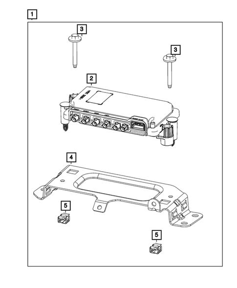 26. Camera Processor Module
 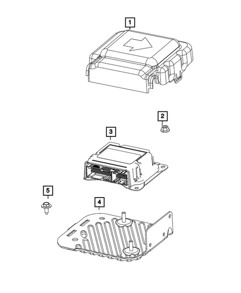 27. Occupant Restraint Control Cover
 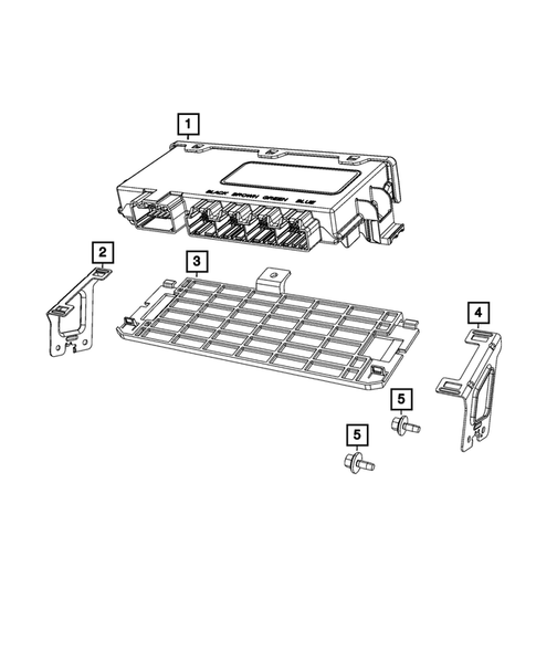 28. Vehicle Systems Interface Module
 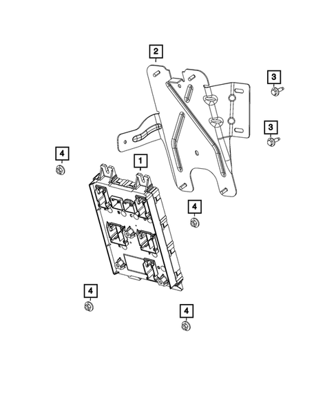 29. Body Controller Module
  30. Gateway Module
  31. Vehicle Systems Interface Module
  32. Air Bag Control Module
  33. Snap In Nut
  34. Park Assist Module
 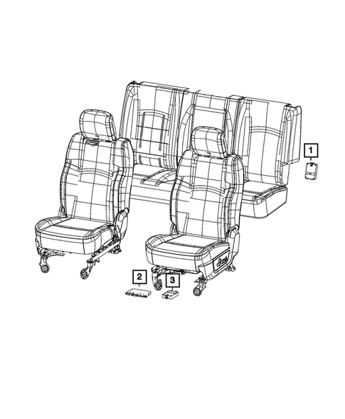 35. Heated Seat Module
 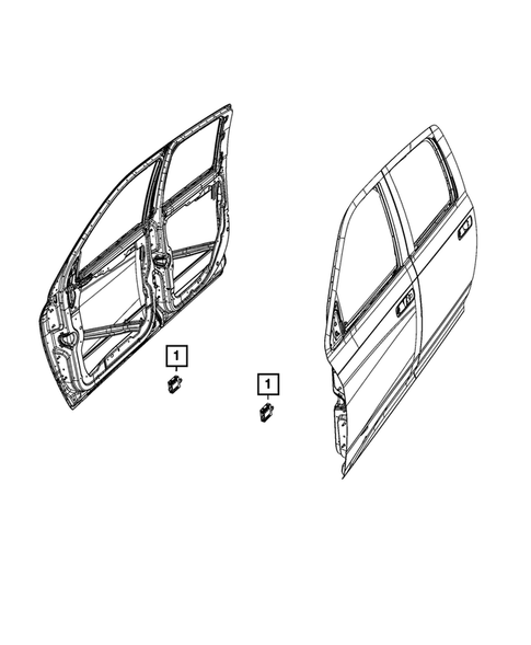 36. Door Module, Right
  37. Alarm Module
  38. Camera Processor Module
  39. Heated Seat Module
 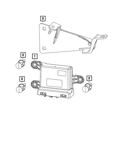 40. Gateway Module
 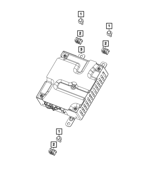 41. Hex Flange Head Screw
 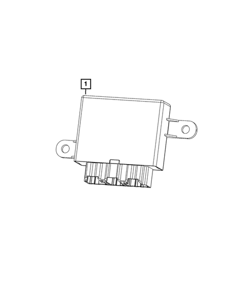 42. Park Assist Module
  43. Door Module, Left
  44. Hex Flange Head Screw
  45. Door Module
  46. Hex Flange Head Screw
 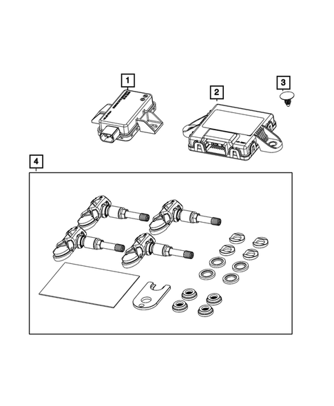 47. Wireless Control Module Receiver
  48. Engine Control Unit Bracket
  49. Park Assist Module
 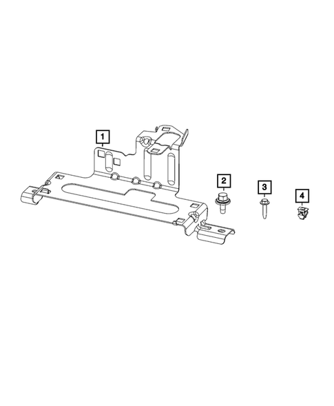 50. Engine Control Unit Bracket
  51. Module Bracket
  52. Anti-lock Brake System Module
  53. Nut And Washer
 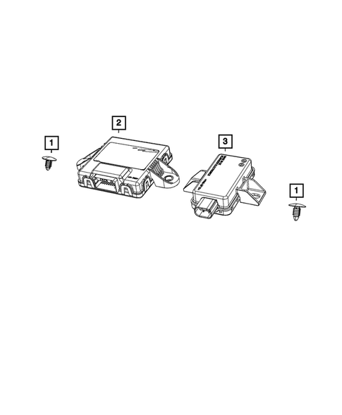 54. Push Pin
  55. Push Pin
  56. Gateway Module, Trailer Tow
  57. Push Pin
  58. Nut And Washer
 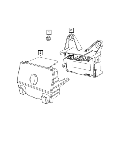 59. Nut And Washer
  60. Module Bracket
 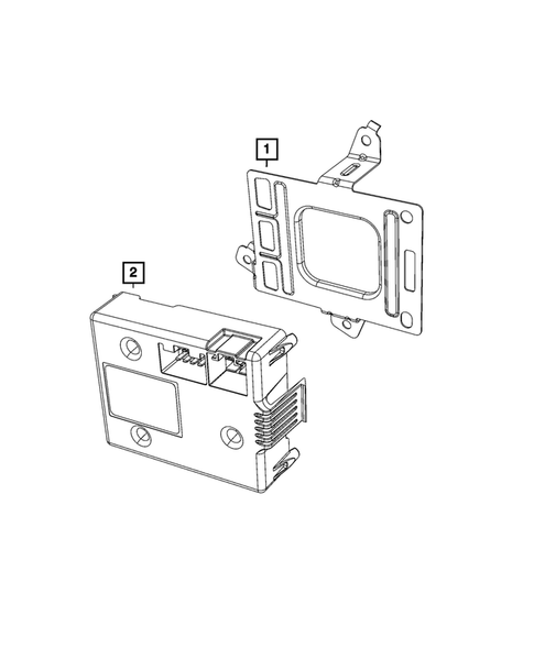 61. Module Bracket
 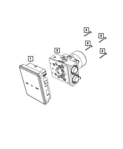 62. Anti-lock Brake System Module
  63. Anti-lock Brake System Module
  64. Module Bracket
  65. Module Bracket
  66. Module Bracket
 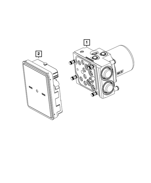 67. Anti-lock Brake System Module
  68. Anti-lock Brake System Module
  69. Transmission Control Module
  70. Transmission Control Module
 No.
Part # / Description / Price
Price
1

Push Pin  Mopar
Mopar
Mopar Description: Used with Shields. Cowl Panel attaching. Cover, Deck Lid Attaching. M6.3X18.60. Shelf To Body. M6.3X18.60. Rear Liner To Body. M6.3X18.60. Cowl Top Attaching. M6.3X18.60. Cowl Grille Attaching. M6.3X18.60. Close out panel attach. M6.3X18.60. Cowl Grille To ...
Not For Sale
Not For Sale
2

Gateway Module Mopar
Mopar Description: Trailer Tire Pressure Monitor Gateway. TTPM Gateway.
MSRP $162.00
$113.46
MSRP $162.00
$113.46
3

Wireless Control Module Receiver Mopar
Mopar Description: Trailer Tire Pressure Module.
MSRP $131.00
$92.22
MSRP $131.00
$92.22